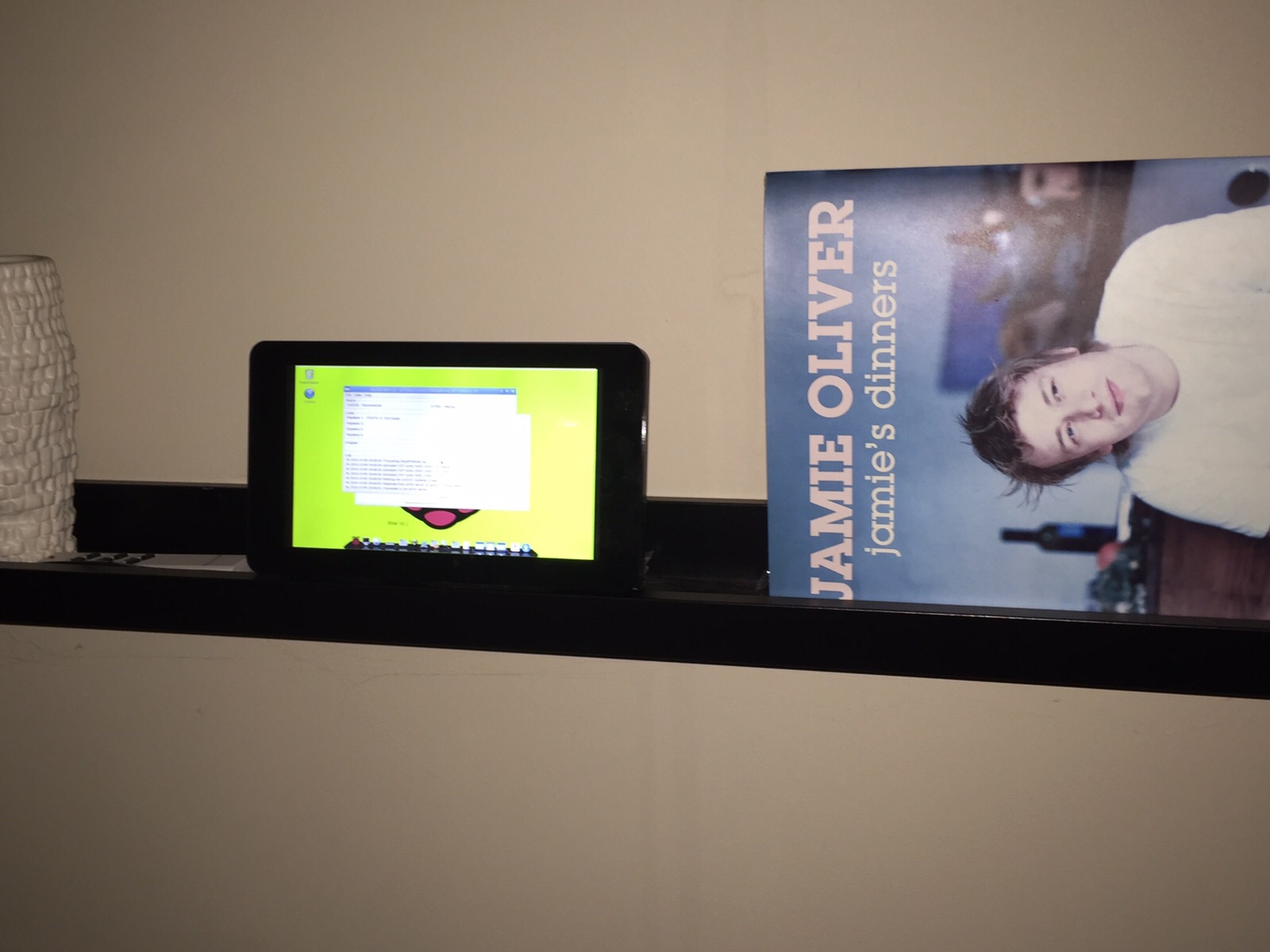
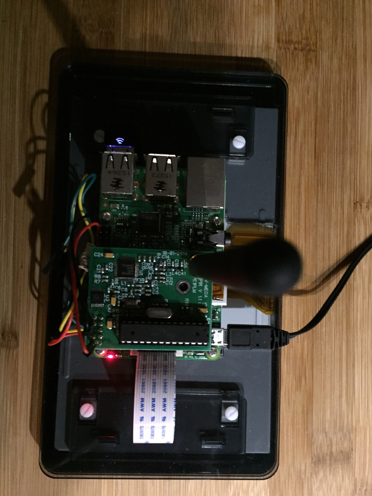
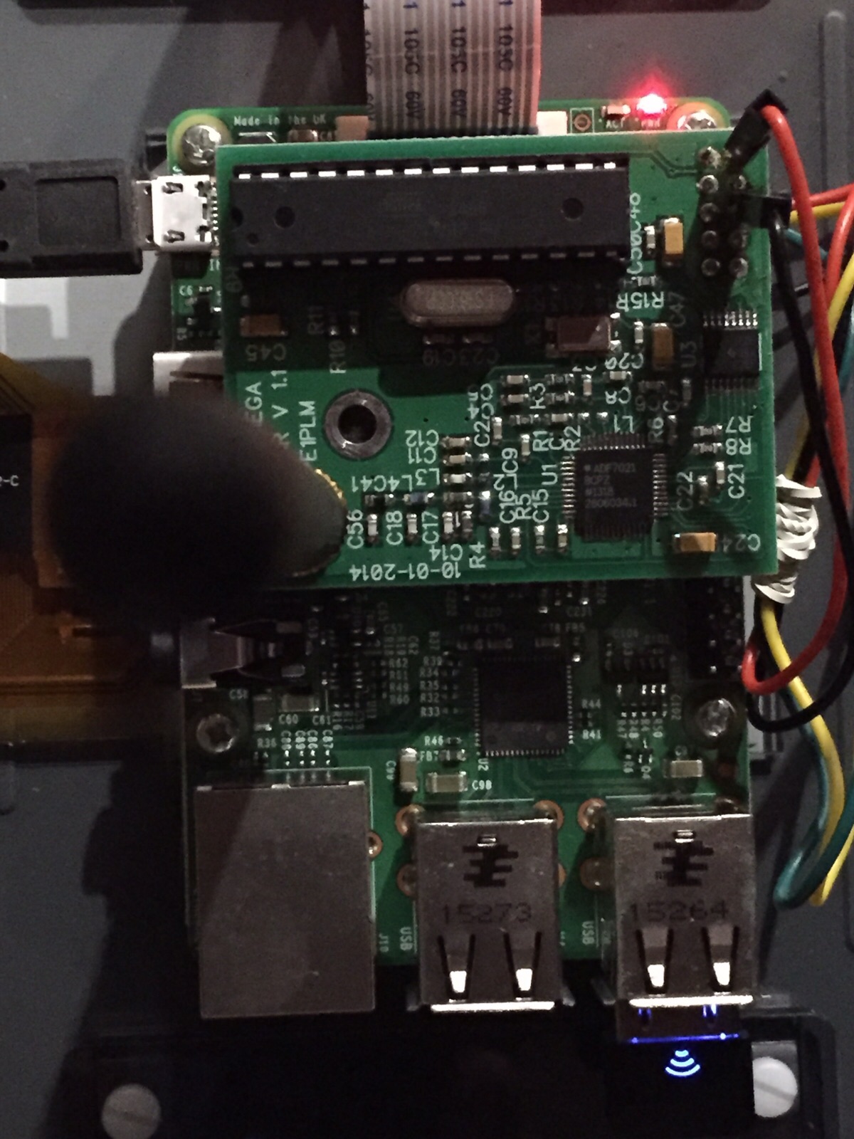
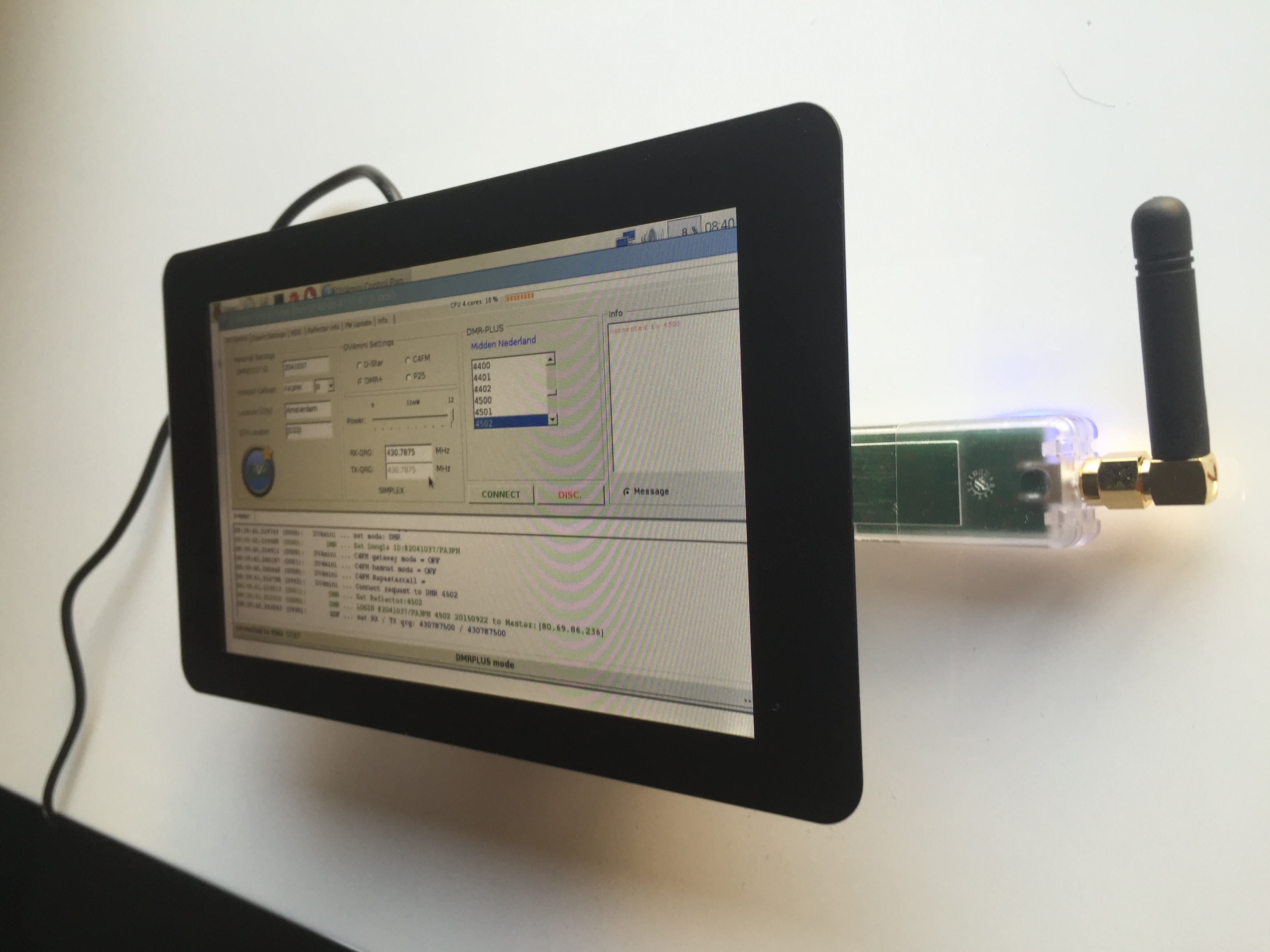
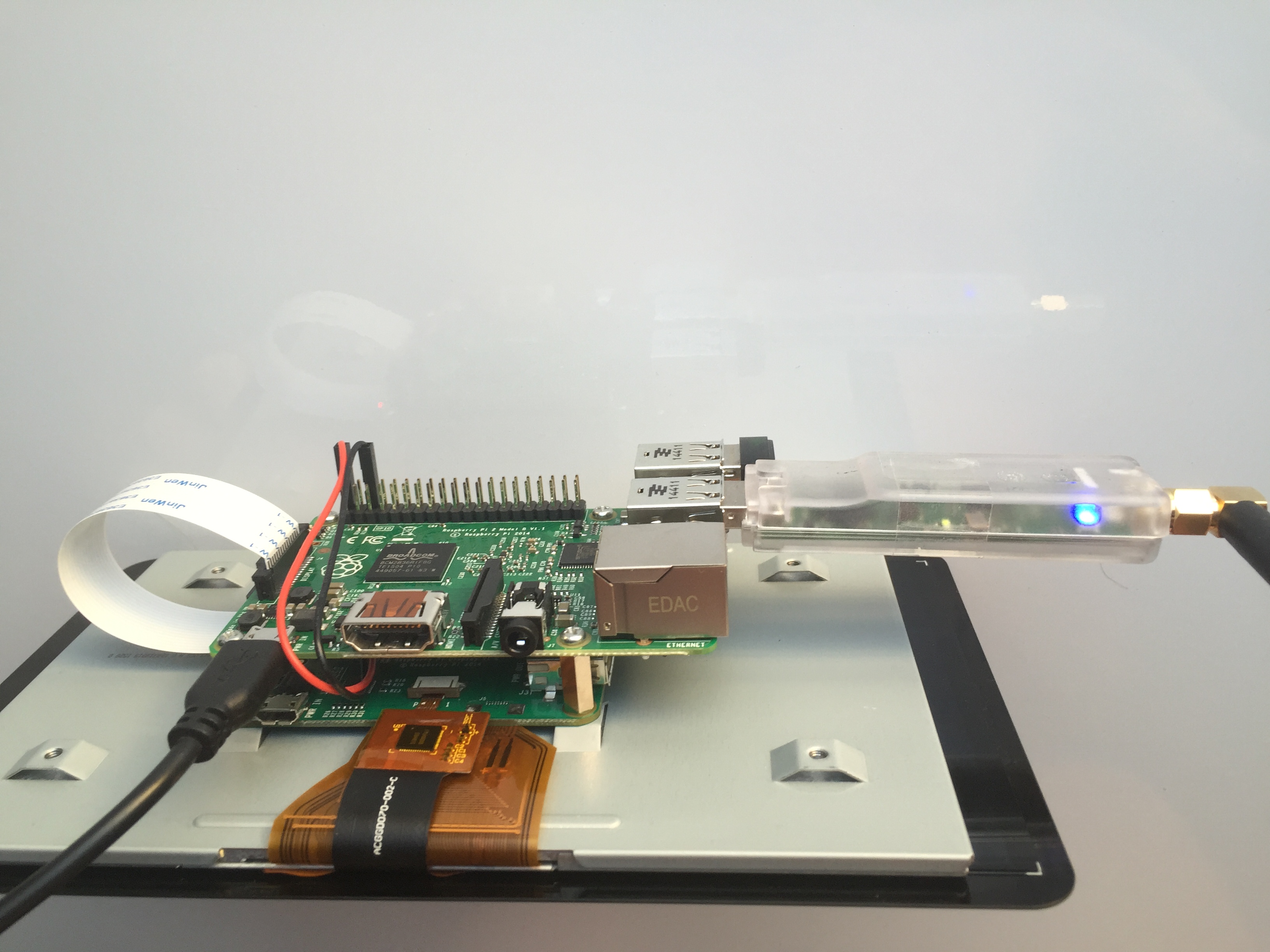
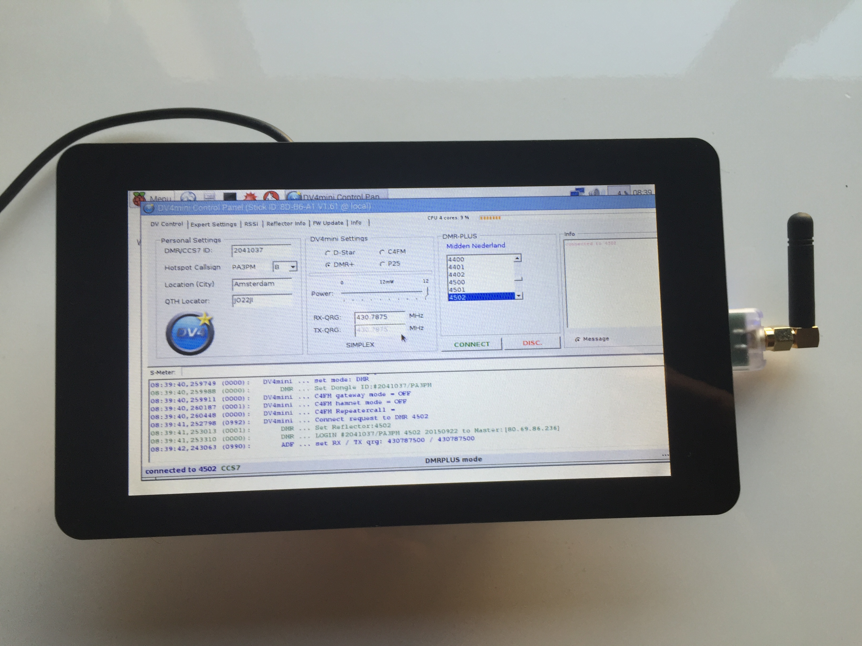
 De feestdagen komen er aan en mocht niet nog niets op je lijstje hebben dan is dit misschien iets. Met deze kit bouw je je eigen PI Laptop met voldoende ruimte er in voor een DVMEGA of DV4mini.
Bron: Makezine.com
Funded on Indiegogo earlier in the year, the Pi-Top is a Raspberry Pi powered laptop. It has a 13-inch screen and an advertised 10 hours of battery life. The Pi-Top comes as a kit that you’ll need to put together, and costs $299 (or $269 without the Raspberry Pi).
Pi-Top is currently shipping laptop kits out to their crowdfunding backers, and in the lead up to the crowdfunding campaign for their new desktop kit now live on Indiegogo, they sent me one of the kits. This is the story of my build.
The Build

Unpacking the Pi-Top needs to be done carefully, the components are packed in foam, nested in a stack, and it’s easy to miss pieces. This is especially true for the cables to connect the Hub to the Raspberry Pi, which are in a ‘hidden’ compartment, and the slide-in cover which goes in the slot behind the keyboard. The cover is buried at the bottom of the box, and is coated in the brown paper that’s typical of laser cut plastic, and pretty easy to miss as a result. So easy in fact, that I didn’t find it right until the end of my build.
The laptop kit comes in three main parts: the base, which contains the battery sealed behind a metal cover plate, the base top, which hosts the keyboard, and the screen, which comes as a self contained unit with a connector.
The guts of the kit come as a hub board, which handles connecting to both the keyboard, the screen, and the battery charging, and a Raspberry Pi 2.

The very first thing that you need to do is attach the screen to the base, these two parts clip together using the hinges. Once snapped together a small screw on the underside of each hinge needs to be tightened to secure the two parts together. It’s pretty easy to over tighten the screw, at which point the hinges will warp and the lid of the laptop will be hard to open. So, if you get strange noises when you open the lid, loosen the screws just a bit.
The next thing you need to do is attach the Hub, and the Pi itself, to the base. This is actually one of the stumbling blocks of the build as the kit comes with two types of “screws,” referred to in the instructions as PCB screws and PCB spacers, and its pretty easy to mix the two up as they look the same in the black and white instructions provided with the kit.

Don’t worry though, it’ll become immediately apparent you have the screws and the spacers the wrong way around when you try and attach the board. It just won’t work if you have them swapped around.

The base comes with magnetically attached covers which come off fairly easily using a small screw driver to pry them away from the board. Insert the screw driver in the join between the the two halves of the cover rather than along the sides, revealing a slot which is where you attach the Hub and Pi boards to the base itself. For reference, the silver appearing ones are the screws, which you’ll use to attach the boards to the base, and the brass ones are the spacers, that should be attached directly to the boards themselves.
Once the Hub board is attached, plug the black connector cable that’s dangling from the screen into the slot on the board.It’s pretty hard to get this cable the wrong way around as the locking bar will guide you. The instructions say to attach this cable before attaching the Hub to the base, but having done that I had to detach it again whilst I was securing the Hub.

The next step is to attach the Raspberry Pi to the Hub. This is done with three cables, an HDMI cable for video and audio, a micro USB cable for power, and a GPIO breakout cable. You should also plug the included WiFi dongle into the Pi about now, if you don’t it will be a bit of a pain to do so later.
In my opinion, the GPIO breakout cable is the thing that will cause you the most confusion when building your Pi-Top, because it’s almost impossible to figure out which way around to fit it, and if you get it wrong bad things might happen.

The Hub end of the cable is pretty simple, there’s a notch, you need to make sure the notch lines up with the pin. Unfortunately the end that attaches to the Raspberry Pi is tricky to figure out.

There doesn’t seem to be any handedness to the cable, the instructions show the breakout wires going back, towards the screen, but at least on my cable the wires came more-or-less vertically out of the headers. After finishing the build I eventually broke out my voltmeter to make sure I had the cable the right way around.
From here on in the build came together pretty quickly. The next thing to attach is the keyboard, there are two cables here, the power control cable which connects the power switch on the keyboard to the Hub and a USB cable which goes to the Pi and connects the keyboard itself.

Next you need to snap the keyboard onto the base. If you thought the hinges were a bit loose, this is the stage when everything tightens up as the back of the keyboard is attached to the same hinge connectors as the screen.
Attaching the keyboard needs both care, when attaching the keyboard to the hinges, and brute force — more than you’ll probably be comfortable with — when pushing the keyboard down onto the ball head screws that secure the edge. It’s probably the trickiest part to get right. Take your time and apply the brute force around the edges only when you’re sure things are lined up at the hinge end of things.

We’re almost done. The final step is to slide the acrylic panel into the slot on the left, to cover the guts of the Pi-Top. This piece was buried at the bottom of the box, and since it was cardboard colored, I missed it and had to go back to the discarded box to look for it.

Once you’ve removed the paper coating from the cover it slides right in, and covers the guts of the laptop.

That’s the complete build. Now it’s time to power up the Pi-Top and see if you’ve managed to put everything together correctly. There really shouldn’t be much of a problem here since, apart from the GPIO breakout cable, there’s little opportunity to get your cables the wrong way around.
Plug in the mains adapter, this should wake the battery up from shipping mode, however this could take more than the “few seconds” mentioned in the manual. In any case, eventually the green LED underneath the power button (located above the slide in cover, slightly to left of centre) will start to pulse. Push and hold for a couple of seconds and you should be greeted by the screen coming to life.
The first thing you’ll see is the multi-color test pattern typically seen when a Pi boots, followed by the scrolling Linux boot messages — you did remember to slot the SD card into your Pi, didn’t you?

The normal Linux boot messages will eventually get replaced by a custom progress bar and the laptop will boot into the Pi-Top dashboard. From here you can create an account, and connect the laptop to your wireless network.
The Dashboard

The Pi-Top will initially boot into its custom dashboard. This dashboard has general settings, along with easy access to some applications, as well as the normal desktop.
With default shortcuts for Minecraft and Pi-Top’s own CEED Universe, advertised as a “gamified method of teaching while following the GCSE curriculum,” it’s obvious that the Pi-Top has been aimed squarely at the 13–15 age range. Like the Pi itself, the Pi-Top originates here in the UK, and for my American readers, 5 GCSE passes at grade C or higher are considered to be roughly equivalent to a US High School Diploma, without Honors or ‘Advanced Placement’ classes.
Rough Edges

It’s here where I started to run into some rough edges. While I was initially asked if I wanted to customize the dashboard, the panel that would, in theory, let me change this customization later didn’t work correctly. Despite being logged in, it insisted that I needed to “Please log in to edit.”
I was also prompted to download an update to the Pi-Top’s operating system. I knew one was pending as the company had sent me an email, so I went ahead, but the update hung at “Connecting…” and didn’t proceed. In the end I had to install the update from the command line.
Unfortunately the way Pi-Top advises you to do this is by using curl to pull a script,
% curl -sL https://www.pi-top.com/download/patch1 | sudo bash -
and pipe it directly to a root shell. This is isn’t great and has rather nasty security implications. I pulled the script and read it, but not everyone — especially not the age range the Pi-Top is targeted at — is going to have the skill to do that.
These, however, can be considered teething troubles. They’re not major problems. Although if you’re aiming at an education market everything needs to work out of the box, since even seemingly minor problems can stall and frustrate a child who is new to computing.
What did I think of it?
The Pi-Top is solidly constructed. It feels like it will survive a good bit of abuse, and as any parent can tell you, it’s going to get a lot of abuse if it’s used by its target market.
My only real complaint with the hardware is that the keyboard is a bit too robust — I haven’t had to hammer at a keyboard this hard since I stopped using a mechanical typewriter.
The build process itself is fairly involved, and the manual is aimed squarely at adults (think IKEA furniture instructions). Certainly, it was beyond my son’s current abilities. That’s not a complaint, it’s obviously targeted at children a little bit older than my son, although I feel even a 13 year old might have problems with the current instructions unless closely supervised by an adult.
There’s space between the Hub and the Pi boards for a half-sized breadboard, and the Pi’s GPIO pins being broken out to a connector slung underneath the Hub. While that connector is placed conveniently to connect to a breadboard, there isn’t a breakout cable provided to connect to a breadboard, nor is the connector labelled particularly well. I’m guessing this might be covered in the CEED Universe application, but it’d be nice to have things better labelled in hardware.
There are also some rough edges in the software interface, although I figure these will get ironed out soon. However, at least during my initial look, there don’t seem to be any show stoppers.
If your child is in the target age range, say around 13 or just a bit older, they will already have access to other hardware, their own laptop, an iPod touch, or iPhone. The main reason they might want a Pi — at least as far as I can see — would be to learn how to program or to hack with hardware, so you should bear that in mind when considering it.
For slightly younger children, and my own son is slightly younger, I’d probably recommend something like the Kano Kit. At least on the software side of things, it seems like it better suits the 6–10 year old age range.
That said, the Pi-Top keyboard and touch pad is far superior to the Kano Kit’s keyboard, which my son finds frustrating to use, especially when playing Minecraft. One thing I’m going to try soon is using Kano OS with the Pi-Top hardware. If that works I can see the Pi-Top replacing my son’s current set up.
Summary
Overall, I like the Pi-Top. The solid construction means that you can give a younger child “their own laptop,” and it’ll survive the experience. For slightly older children it’s a good, self contained way to get them started with programming or hardware hacking and keep everything in one place.
