Klik hier voor meer informatie!
Category Archives: Digital Voice
Nieuw de Hytera K965
Op 31 maart plaatste Hytera dit bericht op haar website, leuk!?
Introducing the new Hytera K965
Hytera are proud to announce the release of the innovative and highly anticipated K965 Dog Collar Repeater.

With an in-built bark-amplifier and canine health diagnostics, the new Hytera K965 can extend your DMR radio network and re-transmit critical messages with complete flexibility when the lightweight repeater collar is attached to your pooch.
Designed to withstand the elements, this IP67 certified device utilises the latest battery technology to deliver 14 hours of operating time. Boasting a dual microphone and powerful 4W speaker, the K965 can also transmit, broadcast and amplify dog barks to improve situational awareness. 40 bit enhanced encryption as standard ensures that any transmission is always secure.
With Dog GPS enabled, you can always keep track of your four-legged friend, whilst the Dog Down and Emergency Dog Alarm ensure that a message is raised if an incident were to occur, sending the location via the DMR data service to other Hytera radio users.
The K965 introduces, for the first time, a health diagnostics tracker. With sensors on the underside of the collar, algorithm-driven diagnostics provide in-depth health data in real time via the DMR network, automatically from the collar.
Simple to adjust, this universal collar repeater is easy to attach and comfortable for your dog, ideal for canine security and policing teams looking to extend their coverage, improving their communications and control.
To request more information about the Hytera K965 please e-mail marketing@hyterauk.co.uk with the subject line ‘April Fools’, or visit this RD965 page to learn more about our real, easy to deploy, outdoor repeater.
Nieuwe BrandMeister repeater actief PI1AMF
Sinds gisteren is de DMR repeater PI1AMF uit Amersfoort verbonden aan het BrandMeister netwerk. Hierdoor is de dekking rond Amersfoort verder uitgebreid! Na PI1EHN weer een prima aanwinst voor het BM netwerk en de Nederlandse gebruikers. Enkele codepluggen onder bestanden op deze website zijn reeds bijgewerkt met deze nieuwe repeater.
 204311 204311 |
PI1AMF Amersfoor | Motorola DR3000 | R02.20.12 | 438.175 | 430.575 | 1 | Slot 1 & 2 linked | 2042 |
Beginnen met Software Defined Radio
Bouw een Digital Mobile Radio Repeater deel 2
Bron: rs-online.com
Adding UHF radios with cooling, a Raspberry Pi for the MMDVM host, plus power distribution and neatly packaging it all in a rack mount enclosure.
This series of posts covers the building of a Digital Mobile Radio (DMR) repeater for amateur radio use on the 70cm band (UHF). The first post in the series introduced DMR basics, before then moving on to the construction and programming of a modem platform based around an STM32F446 NUCLEO board plus an interface shield.
Requirements

For the radio side of the repeater we’ll be using a pair of second-hand Motorola GM340 vehicle radios, with one operating in receive for repeater uplink and the other transmit for downlink. We’ll also need a duplexer to connect both to the same antenna, but since the design of this can vary depending on the repeater uplink/downlink spacing or “shift” — the smaller this spacing is, the larger the duplexer physically becomes — being used, we’ll keep this as an external component.
Along with the radios we’ll also need to accommodate:
- Cooling to enable the radios to operate with a high duty cycle
- The MMDVM platform covered in the previous post
- A Raspberry Pi host for the modem
- An LCD screen for repeater status
- 12V → 5V DC/DC power supply
- Power distribution
Plus also some connectors on the rear of the enclosure and simple controls on the front.
Components

We settled on an RS Pro 4U ventilated rackmount enclosure (665-7722) to house everything, as this should give us enough space with a little to spare, and can be neatly installed in a rack cabinet. This comes supplied with a number of rails to which mounting plates can be attached and secured in place at varying height within the enclosure. Plus also front and “inside front” panels which give more mounting options for front panel controls and connectors.
Rear panel

On the rear panel we fitted:
- Neutrik panel mount female/female RJ45 (909-3714)
- RS Pro panel mount USB Connector (862-1579)
- RS Pro 2 Way Female Feedthrough HDMI Connector (124-6388)
- Neutrik panel mount 3-way XLR female connector (405-736)
- 3x RS Pro panel mount 50 ohm BNC female/female (546-4083)
- ebm-papst 12V DC axial fan (136-0665)
- 119mm fan filter (507-905)
The nice thing about using XLR form factor connectors for Ethernet, USB, HDMI and DC power is that you have standard cut-outs for mounting — keeping it nice and simple.
Although at the present time we only require an RF connector each for transmit and receive, we decided to add a third just in case we needed it for future use. E.g. to connect up an antenna for a GPS disciplined oscillator (GPSDO) for increased frequency accuracy and stability.
For the cooling, a high quality ebm-papst fan plus filter was selected, as the equipment will be operational 24/7 and overheating could prove catastrophic for the radios.
Internal

Internally we have a base plate laser cut from 5mm black acrylic, with one of the radios mounted to this, along with the MMDVM modem, a Raspberry Pi (137-3331) host and a length of DIN rail. Two of the mounting rails supplied with the enclosure are then used to provide a higher level on which to mount the second radio via another laser cut acrylic plate, above the first radio.
The following components will be secured to the DIN rail:
- RS Pro Red DIN rail terminals (501-821)
- RS Pro Black DIN rail terminals (501-976)
- Jumper bar to gang together the above (399-105)
- Omron 8 Pole Relay Socket (329-884)
- Omron DPDT Non-Latching Relay Plug In (828-7268)
- Omron Retaining Relay Clip (466-447)
- DIN rail PSU Vin 9 → 36 V dc, Vout 5V dc (896-2209)
The DIN rail terminals together with the jumper bar will provide the basis for power distribution, with the relay switching this via front panel control. The DIN rail PSU will be used to take a common 12VDC supply and switch this down to 5VDC for the Raspberry Pi and modem.
Front panel

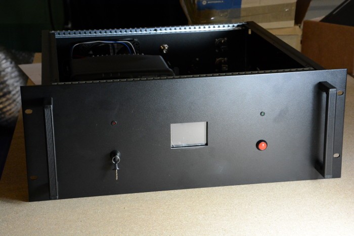
On the front panel we have a cut-out for the LCD which will display repeater status. This is secured to the inside front panel, which also has cut-outs to route cables through to the internal section.
Mounted in the front panel we have:
- C & K key switch (863-6944)
- RS Pro panel mount red LED (700-1855)
- Otto DPST-NO/NC Momentary Push Button Switch (433-3168)
- RS Pro panel mount green LED (700-1845)
The key switch will be used to supply 12V to the relay coil and in turn to power up the repeater, with the red LED wired as a power indicator. The momentary push button will be used to trigger the Raspberry Pi to shut down and the green LED will be used as a “run indicator”.
One option would have been to configure the Raspberry Pi to use a read-only filesystem, but then it wouldn’t be able to log debug info which might prove quite useful in operation. Hence with a read/write filesystem the need for some mechanism whereby the Raspberry Pi can easily be shut down, without the need for a keyboard and monitor to be attached.
Fitting

One of the nice things about the enclosure is the supplied rails which can be mounted at varying heights, giving us more options for arranging everything. Previous experience has told us that you tend to need more space than originally anticipated and this is particularly true once you start adding things like USB cables, where the connectors can quickly use up a lot of space. As such it’s easy to see how our enclosure will begin to fill up in due course.

Above you can see how we mounted the small LCD to the inside front panel, via four screws and small spacers. Large holes were cut in this to route cables from front panel controls and indicators.
When it comes to cutting out the front and rear panels it’s definitely worth taking your time and carefully planning this. Round holes up to 10mm or so are easily drilled and above this size we tend to use sheet metal punches, as these give a much more satisfying finish to hole cutters. Although the hole for the fan in the rear panel was cut using a rather large hole saw.

The key switch and LCD required a more unusual shape and a rectangle cutting out. The main bore of the keyswitch was drilled and then filed out, using a laser cut piece of MDF as a guide/template. The rectangular window for the LCD was “chain drilled” and once again filed using MDF templates to achieve the target size and shape.
Next steps
With all the components now secured in place in part 3 it will be time to move on to wiring, configuring the Raspberry Pi and initial testing.


