Bron: www.florian.wolters.de
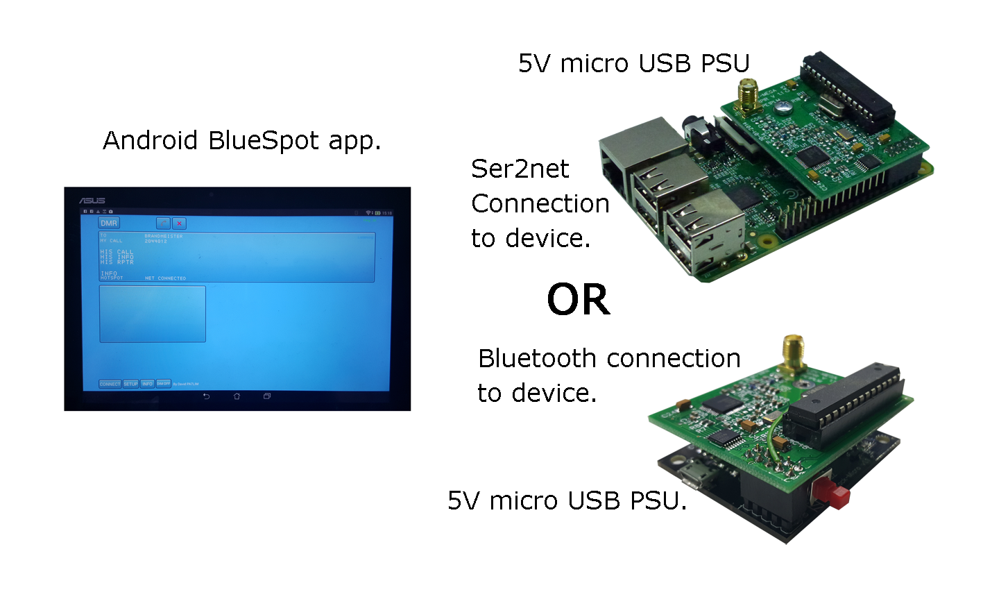
During experiments with digital voice mode in hamradio I discovered a nice project describing an adapter for D-Star, DMR and other digital modes based on an Arduino Due and a little PCB to be put on top. This unit is called the Multimode Digital Voice Modem or MMDVM (see [1]). It seems that this is getting quite popular because hard- and software is Open Source.
The units can be ordered from Bruce, VE2GZI for a very reasonable price. As of writing this the time for delivery was about 3 to 4 weeks. Because this unit was really of interest I decided to build one myself besides having ordered a set of the nice PCBs with SMD parts.
The schematics and some documentation can be found in the correspronding Yahoo Group under [2]. I built the version 1 circuit which currently also delivered if you order one of the PCBs. Alexander, DC5AJ was so kind as to provide me with a prefilled shopping cart from a Germany electronics supplier which I modified slightly. If you want to order the parts, see [3]. All together with a PCB and a cable this is around 18 €. The additionally needed Arduino Due was clicked on eBay for some 15 € – of course a clone and not the original one :).
So that makes just around 30 € for a neat digital voice adapter that runs with ircDDBGateway and DStarRepeater for D-Star for example. As the circuit is a little more complicated than a simple transistor circuit I decided to look for some software that allows for designing the circuit on a breadboard PCB. I decided to go for blackboard as a first try. This software is available as Open Source from [4] and is written in Java and should run on all major operating systems.
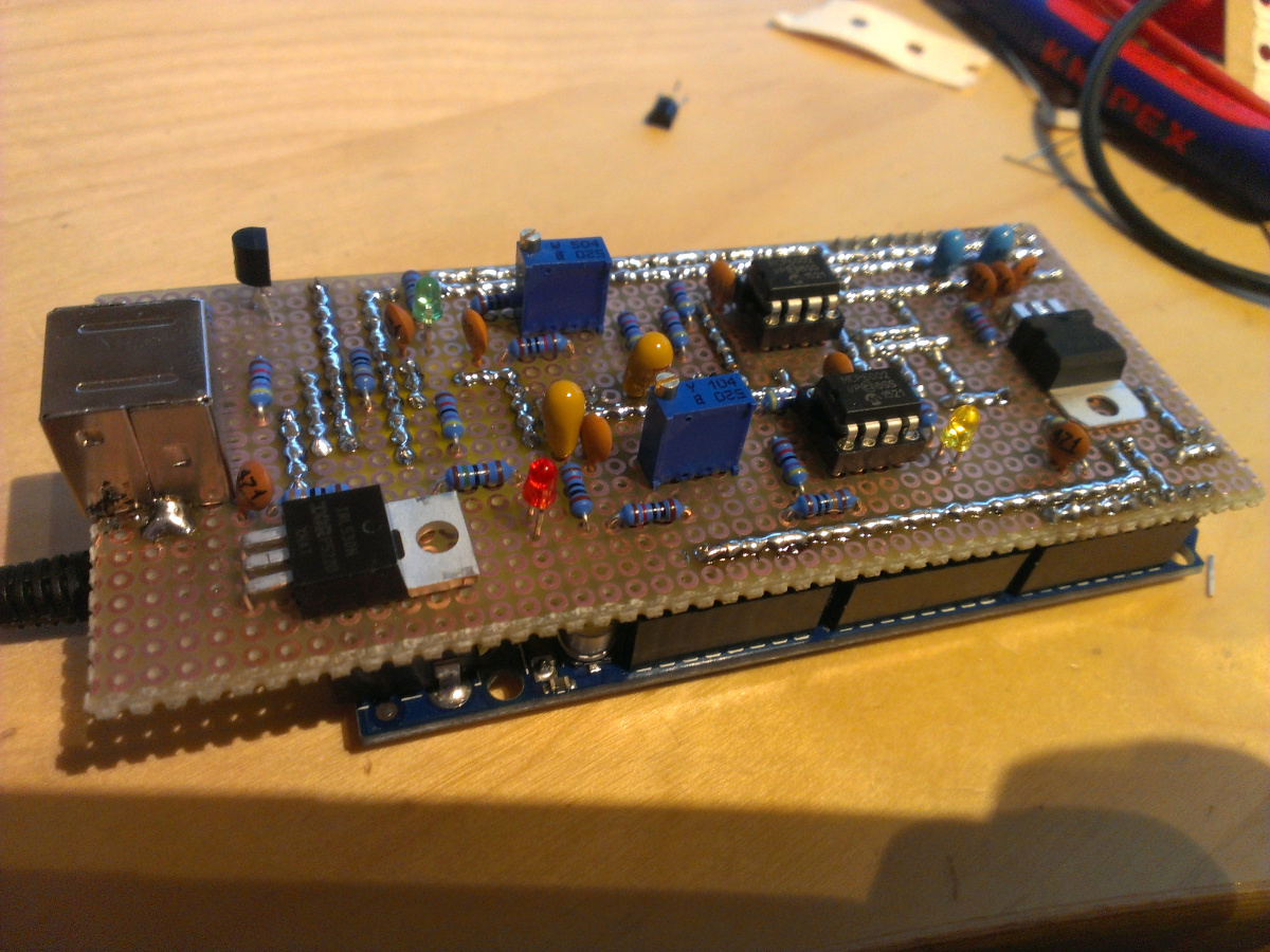
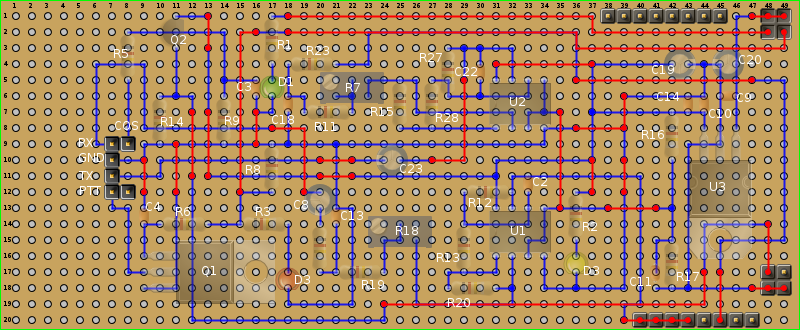
The software allows for basic design of the circuit with basic components without regard to values. I put the parts together on a PCB that is slightly longer than the Arduino. It fits on top as the original MMDVM does. As I had a double layer breadboard I used top and bottom side for wiring. The circuit paths on top are outlined in red and the bottoms ones in blue. There are some areas where the bottom paths are overlayed by the top ones. So for reproducing this circuit I recommand to use blackboard because that allows for blanking one of the layers. The file for blackboard can be downloaded here:
mmdvm.bb
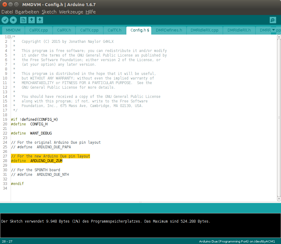
After building the board from the blackboard draft I burned the MMDVM firmware from [5] into the Arduino and running the MMDVMCal program ([6]) I realised that the circuit was not working as expected. None of the LEDs was showing any activity on toggling the PTT. Just the power LED was lit. After some research I found out that there are different Arduino board layouts in the world each having a little different pintout or at least numbering. That issue could be resolved by switching the board layout in the MMDVM Firmware using the Arduino IDE. I just ahd to switch from ARDUINO_DUE_PAPA to ARDUINO_DUE_ZUM in Config.h.
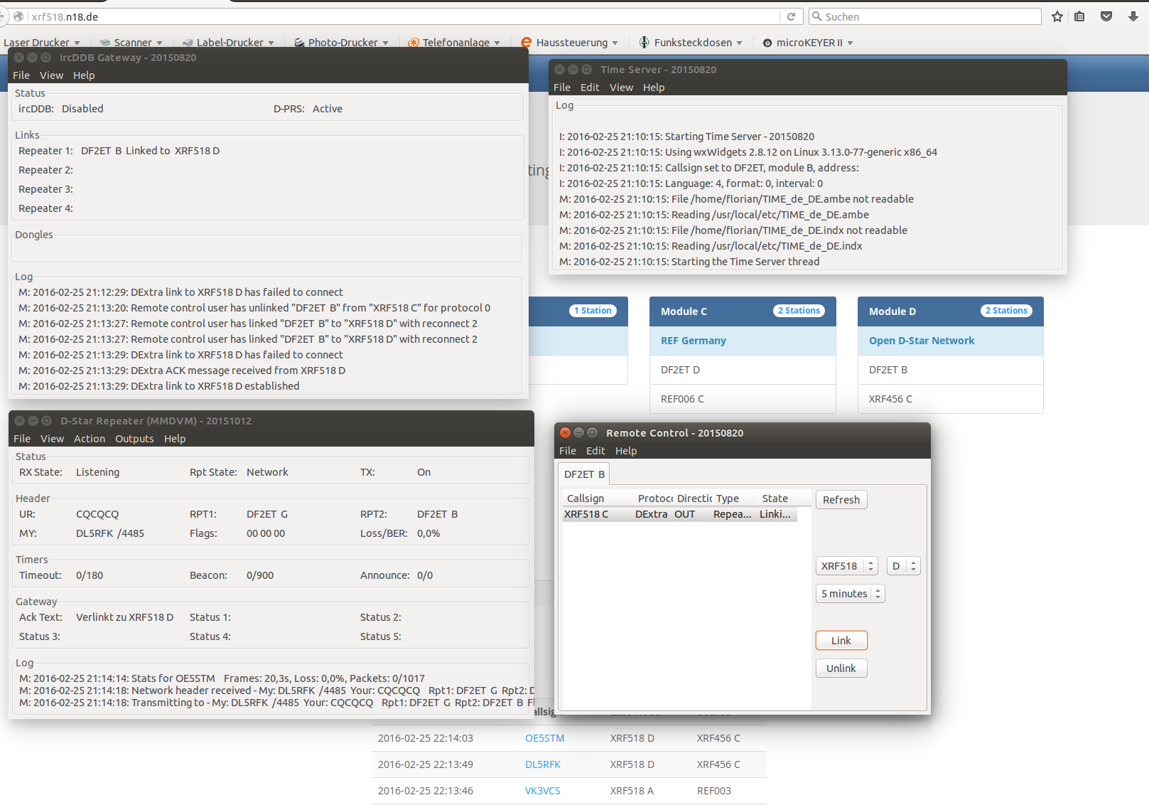
With this modification worked as expected. I used ircDDBGateWay and DStarRepeater from [7] and configured DStarRepeater to use the MMDVM. After compiling I connected it to an XRF reflector to receive some audio. My ICOM R2500 decoded the D-Star QSO instantly while the ID-51 resisted. So I did some turns on the trimmers for TX and afterwards also the ID-51 was fine with decoding.
A little recording of my first QSO using the MMDVM adapter with DL6EAT can be found on YouTube unter [8].
References
[1] http://mmdvm.blogspot.de/
[2] https://groups.yahoo.com/neo/groups/mmdvm/
[3] https://secure.reichelt.de/index.html?&ACTION=20&AWKID=1181237&PROVID=2084
[4] https://github.com/mpue/blackboard
[5] https://github.com/g4klx/MMDVM
[6] https://github.com/g4klx/MMDVMCal
[7] https://github.com/dl5di/OpenDV
[8] https://youtu.be/ydqG4fWbkbw
